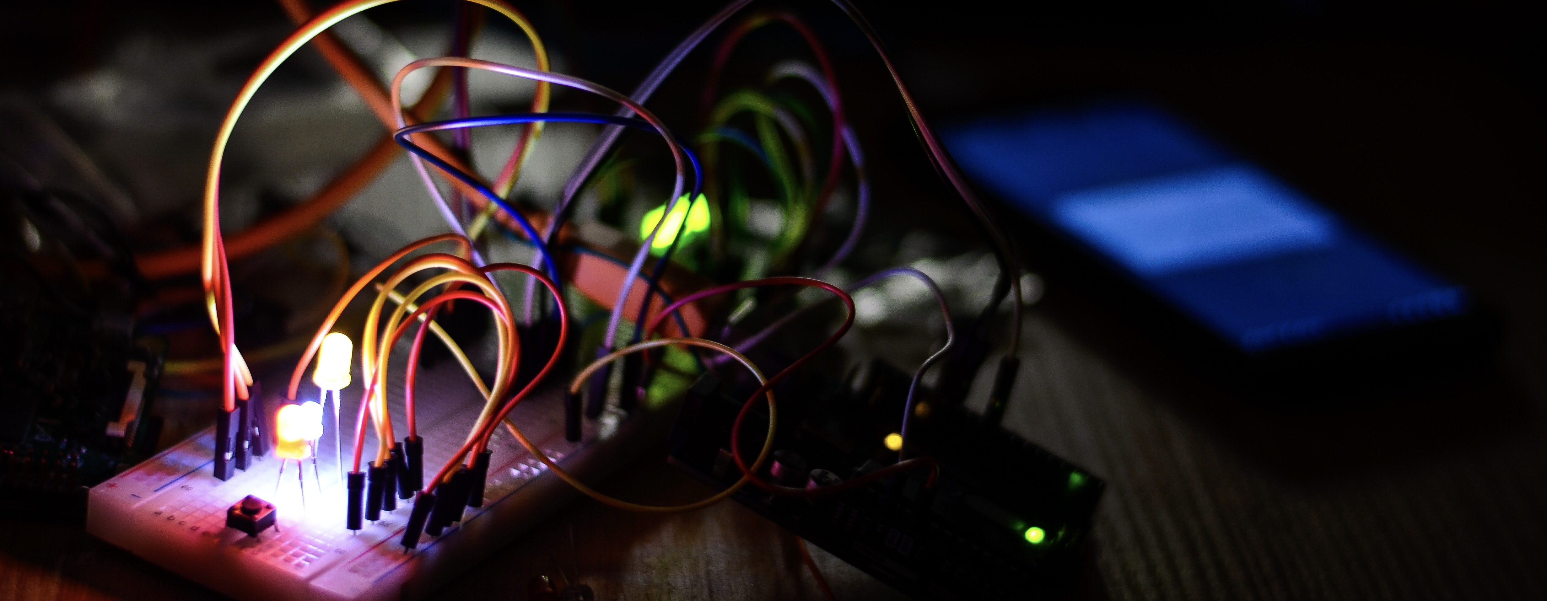
This was a fun project I worked on back in 2016, it started with me learning to use the Arduino micro-controller and quickly developed to an internet-connected Raspberry Pi interfacing to the Arduino over I2C to control a 230V traffic light via a set of opto-isolated relays.
Arduino
The Arduino is a very popular micro-controller that through its integrated development environment provides a very accessible means to get into embedded systems programming. The Arduino Uno board that I have used in this experiment uses 5V TTL signals - for a technical description of what TTL (Transistor-Transistor Logic) means, National Instruments maintains an excellent knowledge base article.
I started with learning how to control LEDs using the Arduino, then relays, LEDs controlled via relays and finally the 230V lamps of the traffic light. The Arduino sketch for this is pretty simple as it just steps through the four phases of a UK traffic light, consisting of:
- Red
- Red, Amber
- Green
- Amber
The sketch is as follows:
LEDs
The following circuit diagram illustrates how to wire up the Arduino to control LEDs. If you’re an electronics beginner you may be wondering why there are resistors between the Arduino and LEDs, this is because the Arduino outputs a 5V signal and the LED which only drops 1.8V can become overloaded by the current that passes from the 3.2V residual voltage - therefore a small (470Ω) resistor is necessary. For a more in depth explanation, I suggest consulting the Wikipedia page on LED driver circuits.
Below is a video of the LED traffic light circuit working:
Relays
The following circuit diagrams replaces the LED and resistor output of the previous with relays.
This circuit renders a pleasing audible click-clacking of relays firing.
Relays and LEDs
The next circuit reintroduces the LEDs and resistors of the first circuit, but they are instead controlled via the opto-isolated relays, these relays will be useful for ensuring safety later when dealing with mains voltage.
Relays and Mains Lamps
The next experiment was to replace the LEDs and their safe 5V DC supply with the traffic light and its 230V AC supply. N.B. Within the traffic light I discovered three 230V to 12V step-down transformers, these allow the light to operate using 12V halogen bulbs.
DISCLAIMER Experiment with mains voltage at your own risk
As you will notice, with an abundance of caution, I retired to the safety of my garden when I attempted this experiment, with the setup connected to a residual current device, just in case I or someone else acted as a return path for the current.
Raspberry Pi
The Raspberry Pi is great example of a single board computer, it has enough resources to even run modern operating systems such as Linux or Microsoft’s Windows 10, whilst providing General Purpose Input and Output (GPIO) pins for interfacing with hardware. Unlike the Arduino Uno, the Raspberry Pi uses 3.3V CMOS logic.
For this part of the project, I wanted to expose a web service running on the Raspberry Pi to the internet. This required writing a web service that provides an interface to remote users to control the traffic light. The received instructions would then be translated into the intended actions upon on the light by setting outputs to high and low signal levels accordingly.
I opted to create a user interface consisting of the below Scalable Vector Graphics-based traffic light, that when clicked, sent control messages back to a nodejs javascript web service via socket.io web sockets
Circuit
Whilst the Raspberry Pi could quite easily control the traffic light relays with its GPIO, I was interested to experiment with the interfacing of the Raspberry Pi with the Arduino via the I2C bus. Due to the differing signal levels (5V and 3.3V) of the two devices, an additional level shifter component was needed to interface the two.
Demo
I registered the domain putonmyredlight.com, setup an A record to point to my public IP and punched a hole through my firewall for the web traffic to access the service hosted on the Raspberry Pi. I then streamed video of the experiment and announced the url on Facebook Live from a mobile device and the below video is the unedited video from the live session. It was great to see people connecting from around the world within seconds of going live to experiment with it.


